


Within the scope of work package 2200, the system architecture for remotely controlled, coordinated driving in inland navigation was designed. First, the system was broken down into its essential modules:
In consultation with the respective collaborative partners, the system variables required for the realization and development of the various modules were tabulated, as well as the information that emerge from the modules. As far as possible, the access mode, data format, resolution, accuracy and update rate were defined. Based on the defined input and output variables, the respective communication parts, transmitter and receiver, were derived. For the definition of the interfaces, adjacent instances, which are not part of the system, were considered in addition to the individual modules of the system.
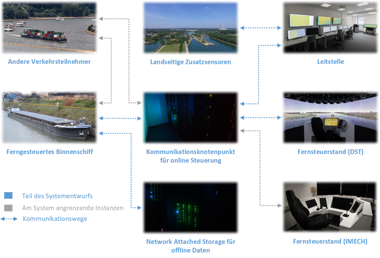
Figure 1 shows the instances that are part of the system and adjacent instances that interface with the system. A central communication node is provided for most efficient communication between the shore side and the ship. Wireless communication between the shore side and the ship is a bottleneck. A central communication node avoids the need for multiple transmissions of data. The central node provides various information to the instances on the shore side.
For remote control and coordination, the modules “Remotely controlled ship”, “Communication node – online control”, “Control center “, “Shore-side auxiliary sensors” and “Remote control stand” are required. The development of individual subsystems requires various data in advance, which will also be generated as part of the project. In order to make the data available, an additional communication node will be provided. This node does not have any real-time requirements. Onshore, this data will be processed and made available in a network attached storage. Individual algorithms will be developed on the basis of this data. In particular, radio communication to other conventional traffic participants will be considered as an interface in the system architecture. In the future, separate protocols for communication with other remote-controlled and automated ships will also be provided.
Communication was defined across all modules: A common logical network is implemented on the ship, remote control station and control center via a VPN. Fixed IP addresses are assigned to the individual modules that communicate with each other. In this way, connection interruptions can also be detected unilaterally by the availability in the network. The “Open Platform Communications Unified Architecture” is used across the board as the standard for data exchange. This architecture is platform-independent and provides diagnostic data for identifying faulty transmissions.